DC motors are quite complex, and you’d be surprised to learn that there is a lot more science behind them that meets the eye. So, how does a DC motor work? Well, that all depends on the way that the mechanism is being used and the type of DC motor in operation.
If you’re curious to learn more about how a DC motor works, continue reading below.
What is a DC Motor?
A DC motor is a device that transforms electrical energy into mechanical energy. DC motors use direct current to convert electrical energy into mechanical rotation.
Magnetic fields created by electrical signals are used in DC motors to propel the movements of a rotor mounted inside the output shaft. The output torque and speed determine the electrical input as well as the motor’s design.
How Does a DC Motor Work?
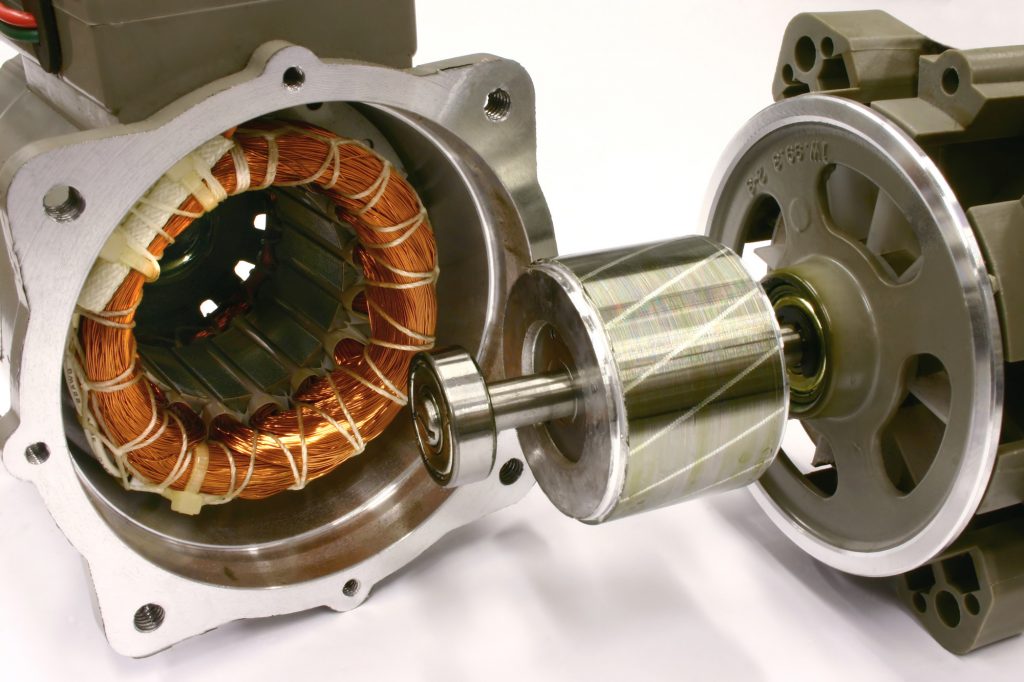
A DC motor’s fundamental working concept relies on the way magnets respond to one another. Similar magnetic poles resist and opposite magnetic poles connect. A coil of wire, known as an armature, and a horseshoe magnet are the essential components of a DC motor.
An electromagnetic field forms and orients to the middle of the coil every time an electric current passes through it. When you turn the current on and off, the magnetic field switches on or off as well.
An electric current starts the process. It’s provided by a battery or a physical energy source. The current travels from the conductor to each end of the coil of wire.
It passes through a half-circle commutator. The commutator’s brushes let the current flow around a copper wire loop across two magnetic poles. The brushes follow the current’s route, passing through the right and returning to the left.
Each wire rotates in the exact direction because the electric current reverses every half rotation. All you’ll ever get without the commutator is a 180° rotation.
The wire propels by a push each time an electric current runs. An upward force is created on the magnet’s south pole, causing the wire to travel upward. A descending force forms on the magnet’s north pole, causing the wire to travel downward. The coil of wire rotates on an axis as a result.
The voltage provided to the armature can regulate the speed of a DC motor. Most of the time, the maximum torque occurs at low speeds. Trams and other electric vehicles are ideal for this purpose.
The Principle Behind DC Motors
“When a current carrying conductor is put in a magnetic field, it encounters a mechanical force, according to the basic operating principle of a DC motor. Fleming’s left-hand rule determines the force’s direction, and F = BIL determines its magnitude. Where B denotes the magnetic flux density, I denotes the current. L is the length of the conductor inside of the magnetic field.
Back EMF
No electricity generation is conceivable until there is an object to oppose the conversion—according to natural principles. This opposition comes from magnetic drag in generators, but back EMF is present in DC motors.
When a motor armature rotates, the conductors sever the magnetic flux lines. As a result, it causes an EMF to induce in the armature conductors. This is according to Faraday’s Law of Electromagnetic Induction. The induced EMF is directed in the opposite direction as the armature current (Ia).
The Importance of Back EMF
The volume of the back EMF correlates to the motor’s speed. Consider a DC motor whose load is abruptly decreased. The needed torque is modest in comparison to the present torque in this situation.
The needed torque is modest in comparison to the present torque in this situation. Due to the extra power, the motor’s speed will begin to increase. Because the back EMF is related to the speed, the magnitude of the back EMF will likewise rise. The armature current then starts to decrease as the back EMF increases.
Because torque is related to armature current, it’ll decline until it is enough for the load. As a result, the motor’s speed is regulated.
When a DC motor is rapidly loaded, however, the load causes the speed to drop. Back EMF drops as speed decreases, enabling greater armature current. To meet the load demand, increased armature current boosts torque.
As a result, the existence of the back EMF causes a DC motor to become self-regulating.
Types of DC Motors
There are different types of DC motors including the following:
Brushless DC Motors
Brushless DC motors, often referred to as electronically commutated motors, vary from brushed motors due to advances in solid state electronics.
Brushless DC motors differ from conventional types in that they lack a commutator. They don’t rely on an electronic servomechanism to sense and change the rotor angle.
Shunt DC Motors
The field windings of a DC shunt motor are linked in conjunction with the armature, making it a type of brushed motor. Due to the parallel windings, shunt wound DC motors have a lower current.
Conveyor belts, hoists, and mixers are examples of applications where a steady torque is required and the weight is not greatly affected by speed.
To learn more about the various types of systems in a DC motor, follow the highlighted link.
Understanding DC Motor Functionality
As you can see, there’s a lot that goes into making a DC motor work. Hopefully, the information above helps you to better understand it.
To read more content like this, continue browsing our website to find additional content.