
Common Automotive Electrical Terms
Understanding automotive electrical terms helps you better understand how we use electricity in modern-day automobiles. Comprehending each individual term and its definition will aid in diagnosis of complex electrical systems. It also makes everyone in the shop think your smart. Knowing what the symbols look like also helps.
The first term to discuss is electrical current. This is the movement or the flow of electricity. The greater the number of electrons flowing past a given point in a given amount of time, the more current the circuit has.
The unit of measuring electrical current is Amps. It’s credited to Andre Ampere who studied the relationship between electricity and magnetism. The instrument used to measure electrical current flow in a circuit is called an ammeter. Automotive meters include this testing function.
In the flow of electricity millions of electrons are moving past a given point at the speed of light. The electrical charge of one electron is extremely small. It takes millions of electrons to make a measurable charge.
For these reasons one amp of current means that 6.28 billion electrons are flowing past this point in one second. There are two types of current. Direct current or DC, and also alternating current or AC. With direct current the electrons flow in one direction only.
In alternating current the electrons change direction at a fixed rate forming a wave pattern. Typically an automobile uses AC from the alternator converted to direct current for charging the battery. This conversion is done internally by the bridge rectifier. Then automotive engineers use the direct current to supply power to the important automobile systems. Most automotive meters measure both types of current flow.
Electrical Terminology for Automobiles
Voltage is electrical pressure. Voltage does not flow like current. It is actually the pressure that causes the current to flow. To have current flow some force is needed to move the electrons down the wiring.
This force or pressure within an electrical circuit can also be referred to as electromotive force. This electrical pressure is measured in units called Volts. 1V is the amount of pressure required to move 1 amp of current through a resistance of 1 ohm.
Again an automotive meter has you covered for measuring voltage found in automobile circuits. An instrument called a voltmeter measures the voltage. People named the unit of measurement for electrical pressure after Alessandro Volta, who in 1800s made the first electrical battery.
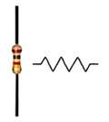
When any substance flows it meets resistance. Mechanics can measure the resistance of electrical flow. We call this unit of measured resistance Ohms.
We credit a German mathematics professor named George Ohm with the discovery of resistance principles. A common symbol for an ohm looks like a horseshoe. Resistance is measured by an ohmmeter.
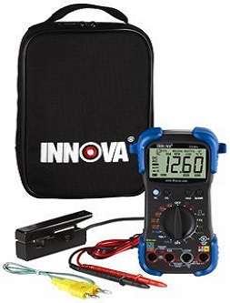
This is why the standard automotive electrical tester is called a multi-meter. Yes, this one tool can measure voltage, amps, and resistance or ohms. Nevertheless, this is one of the most commonly used testers when performing any automobile system diagnosis.
The equus automotive meter comes with a instruction booklet that explains exactly how to use the tool. The model 3340 is the top of the line. It comes with an inductive rpm pickup. The next step down is the 3320. At about half the price for just the standalone meter. Practice makes perfect as the more time you spend with a meter in your hand the more comfortable you’ll be performing diagnosis with it.
Definition of Automotive Electrical Terms
When performing do-it-yourself car repair being a scientist or an electrical engineer is not a necessity. However, understanding the three most commonly used terms above will certainly aid in diagnosis and repair of automotive systems.
When following a standard auto repair diagram they will provide instructions to take voltage readings, resistance measurements and in some cases amperage readings.
The results from the various tests are compared to the factory specifications. Any results that are not within the specified range will indicate a failure or malfunction of that system.
Here is a typical example common on cars and trucks. Let’s say you have set a throttle position sensor code. One of the steps in diagnosis is to check for a 5 V reference signal at the sensor. If there is no 5 V reference at the sensor chances are the TPS is okay.
Replacing the sensor will not solve the issue. More importantly, this gives you a clear path of diagnosis as a failure on the 5 V reference signal circuit. However, following a wiring diagram for this circuit on your specific vehicle eventually uncovers the problem.
Diagnosis and repair of electronics is very important for Diy car mechanics. This next link takes you to more articles about auto electrical systems.
Let me show you a short video that showcases a great method for diagnosing complex electrical problems using automotive wiring diagrams.
You can discover what else we cover on this car fixing website on the homepage. This next link takes you from automotive electrical terms to auto repair advice.